
Geomagnetic Dynamic Simulation Shielding System
System composition
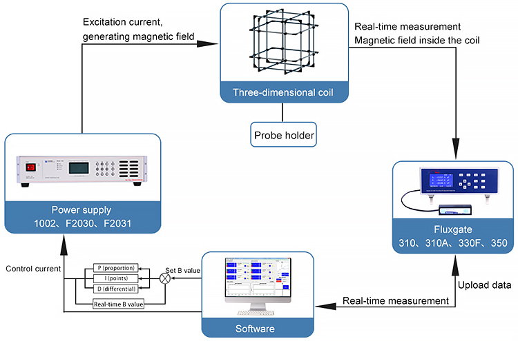
The magnetic flux generating device consists of a set of three-dimensional coils and three corresponding power supplies. A set of three-dimensional coils is used to generate the uniform magnetic field required for the experiment. The three-dimensional coils are equipped with three power supplies to control the three-dimensional coils respectively.
Each dimension has a set of coils to generate a uniform magnetic field. A high-precision imported fluxgate probe is placed in the center as a feedback test for magnetic field adjustment. The feedback signal is calculated by the host computer to adjust the output current value of the high-precision power supply, so as to achieve precise shielding of the geomagnetism and generate the required magnetic field.
The magnetic field measuring device includes the DX-330F fluxgate meter and fluxgate probe, which are mainly used to measure the size of the magnetic field in the uniform magnetic field in the center of the coil and feedback on the real-time magnetic field.
Principle of Software Control
The control of the geomagnetic shielding coil set is used to eliminate the influence of geomagnetism; the control of the coil set in the magnetic field is used to generate the magnetic field of the specified size in the uniform area. External input options can be selected by external signal control magnetic field settings.
When choosing by the external magnetic field control signal set, its working process is: receiving the external control signal to control the geomagnetic shielding coil group, the three dimensions of the set value is set to 0nT, to zero; the geomagnetic shielding coil group three dimensions of the magnetic field value is adjusted to the specified range (+ 50nT), software to send "ready" signal to the control computer and stop zero; the control computer receives the "ready" signal, the user can set the specified dimension values of the magnetic field, such as setting Bx to 1000nT; the received external control signal "Bx:1000nT" after the power generation coil group X dimension control software of magnetic field. The PID closed-loop control Bx control in 1000nT, the user can control precision in the software "sensitivity adjustment of a set; completed the specified dimension magnetic field After adjustment, the software sends the "adjustment completion" signal to the control computer to prompt the user to set the next magnetic field value.
The PID parameter setting interface is shown in the following diagram, which is mainly used to adjust the PID parameters so that the system performance can be optimized in terms of adjusting time, overshoot, oscillation, steady-state error and other indicators.
The Kp addition will reduce the steady-state error and improve the dynamic response speed of the system, but the oscillation frequency will increase when too large. Ki can be used to eliminate the steady-state error of the system. When the Ki is suitable, the system characteristics are ideal. However, the oscillation of Ki is larger than that of Ki, and the integral control has little effect on the system performance, so the steady-state error of the system can not be effectively eliminated. The Kd control can reduce the overshoot of the system, overcome the oscillation and shorten the adjustment time. When Kd is partial, the overshoot changes greatly and the regulation time becomes longer.
PID correction combines the characteristics of lead and lag correction, uses the advance correction to increase the phase margin of the system, improves its dynamic performance, and uses the lag part to improve the static performance of the system, thus improving the stability and rapidity of the system. The PID correction adopts the method of trial and error, and the test principle is based on the principle of first proportion, post integral and re-differentiation, that is, according to the order of P, PI and PID, the satisfactory control parameters are obtained.
Examples(1m )Three-dimensional Helmholtz coil
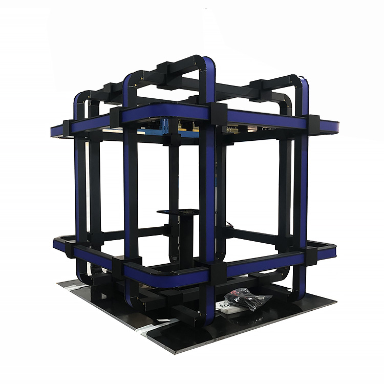
Parameters of the Helmholtz Coil
| Parameter | X-axis coil assembly | Y-axis coil assembly | Z-axis coil assembly |
|---|---|---|---|
| Magnetic field strength | 110μT ± 10μT | 110μT ± 10μT | 110μT ± 10uT |
| B/Icoefficient | 110μT ± 10ut/A | 110μT ± 10μT/A | 110μT ± 10μT/A |
| Magnetic field resolution | 1.1 ± 0.1nT | 1.1 ± 0.1nT | 1.1 ± 0.1nT |
| Continuous service current | 1A | 1A | 1A |
| Instantaneous maximum current | 2.1A | 2.1A | 2.1A |
| Equivalent side length | 1126mm | 1062mm | 998mm |
| Equivalent spacing | 613mm | 578mm | 543mm |
| Direct-current resistance @20℃ | 18.1Ω ± 1.3Ω | 16.1Ω ± 1.1Ω | 14.2Ω ± 1Ω |
| Electrical inductance | ~64mH | ~53mH | ~43mH |
| Weight | 102kg | 102kg | 102kg |
Test dates
| Diameter(m) | 1 | 2 | 3 | 4 | 5 |
|---|---|---|---|---|---|
| Homogeneity range (cm) |
25 | 50 | 75 | 100 | 125 |
| Uniformity | 0.01 | 0.01 | 0.01 | 0.01 | 0.01 |
| Magnetic field(Gs) | 1 | 5 | 10 | 15 | 20 |
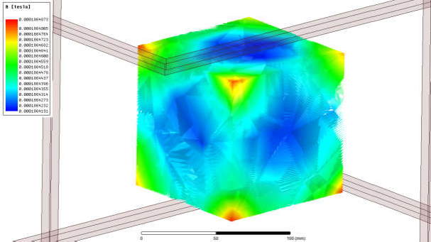
Magnetic field distribution in the 100*100*100 area
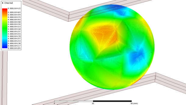
Magnetic field distribution in the Sφ100mm area
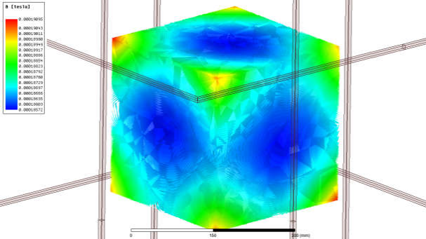
Magnetic field distribution in the 300*300*300 area
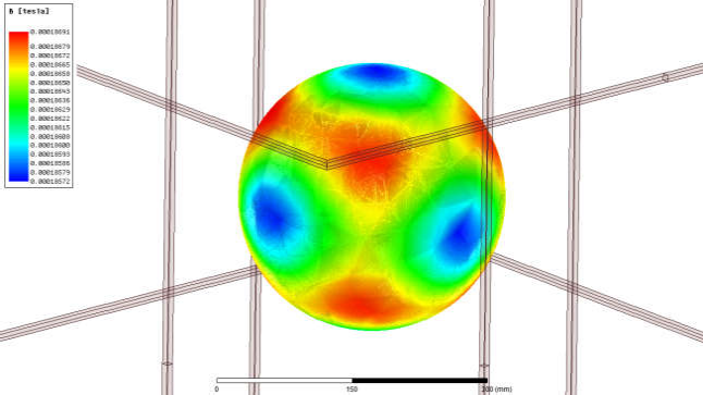
Magnetic field distribution in the Sφ300mm area
