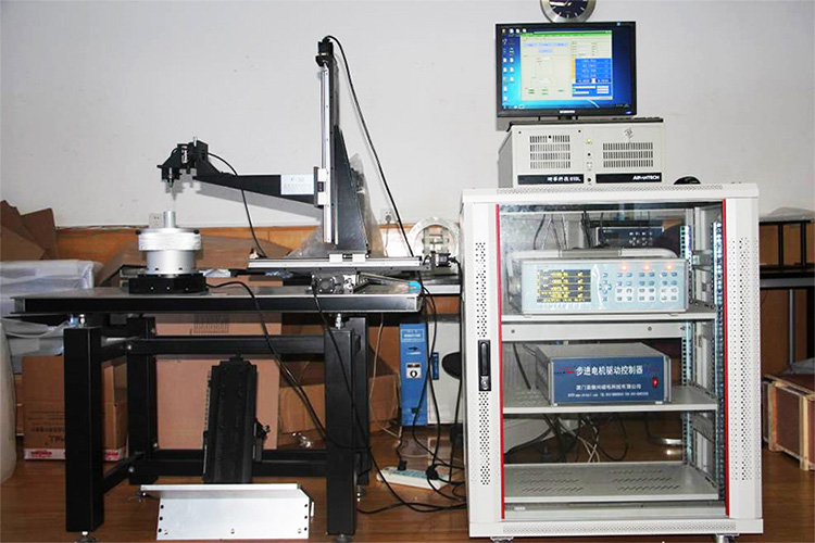
Sample Test of Multi-dimensional Magnetic Field Testing System
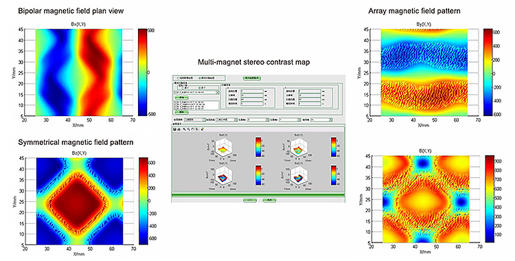
Plane magnetic field
Manual control-When using manual control, the motion table will move the probe according to the coordinate points and positions entered manually. After the movement is finished, the reading is made on the software interface when the reading is stable. It is used to measure the magnitude of the magnetic field at the specified position and is suitable for single-point measurement. Pay attention to the position of the probe when using it. When used in high-precision motion tables, the resolution of motion control can reach micrometers. Flow control-When using flow control, you need to measure the motion path of the stage first. After selecting the path, enter the moving step and the number of steps for each axis in sequence. When the motion table moves, the probe will be moved according to the set path to measure the magnetic field of each point on the path. Flow control is also used to measure the magnitude of the magnetic field on a line in a plane and can be plotted.
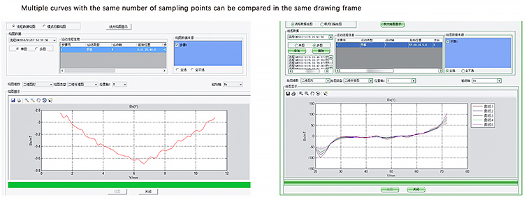
Flow control drawing interface
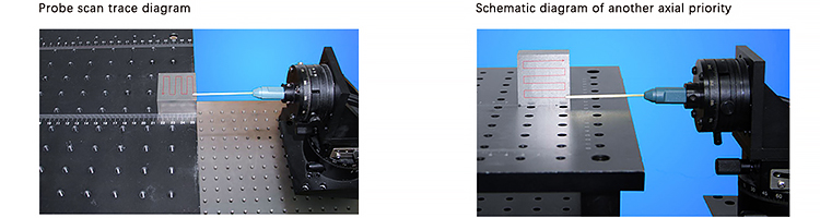
Scan mode - Set the scan area size and the interval length of each scan point as required when using the mode scan. After setting, move the probe to the beginning of the test for manual testing. The scanning process is S-shaped, the scanning path is shown in the figure below, and one axis is performed first.l In addition to horizontal plane scanning, vertical plane scanning can also be achieved by changing the axis of motion. In vertical plane scanning, the scanning trajectory is still S-shaped, and the axial sequence can also be set by changing the axial sequence.
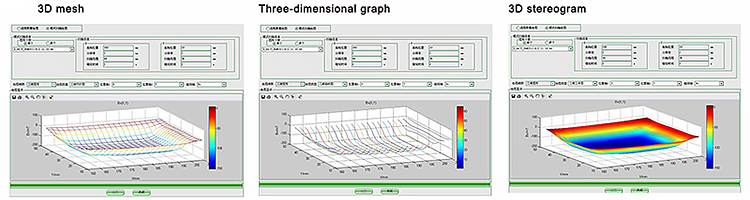
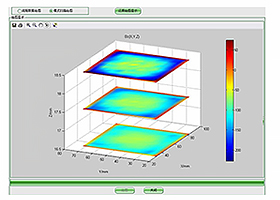
Three-dimensional drawing of space magnetic field(Drawing according to displacement amount, displacement 1mm)
Adding the third axis under the premise of plane scanning can scan different planes to form a set of three-dimensional drawings.
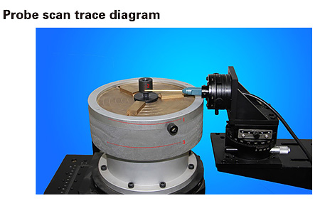
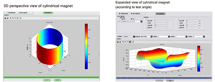
Cylindrical surface magnetic field, motor
Process control-When using process control, you need to adjust the probe to a suitable height and ensure that the probe will not be impacted when the motor is rotating. After selecting the height, enter the moving step and the number of steps in each axis in order. When the motion table moves, the probe will be moved according to the set path to measure the magnetic field of each point on the path. Flow control is also used to measure the magnetic field strength on a perimeter surface around a cylinder.
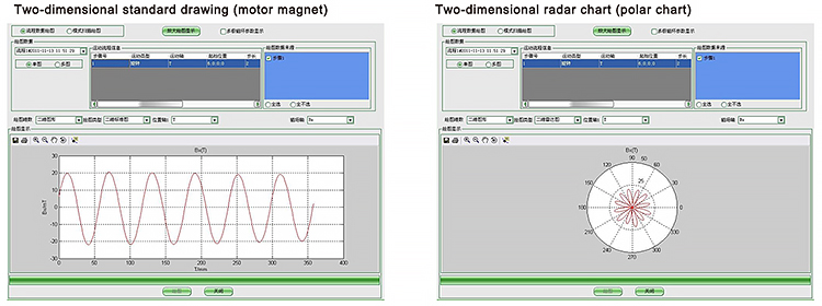
Scan mode - Set the scan surface size and the interval angle of each scan point as required when using the mode scan. After setting, move the probe to the beginning of the test for manual testing. The scanning process is S-shaped, thes canning path is shown in the figure below, and one axis is performed first.
Mode scan drawing interface
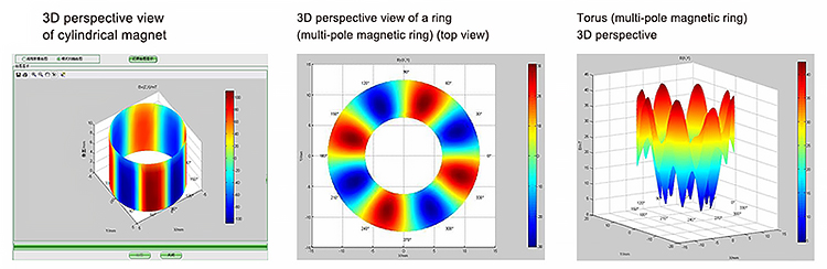
Other special magnets and drawings