
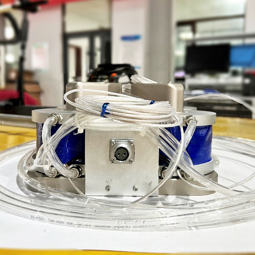
Quality Inspection Report of Quadrupole Clamp Electromagnet
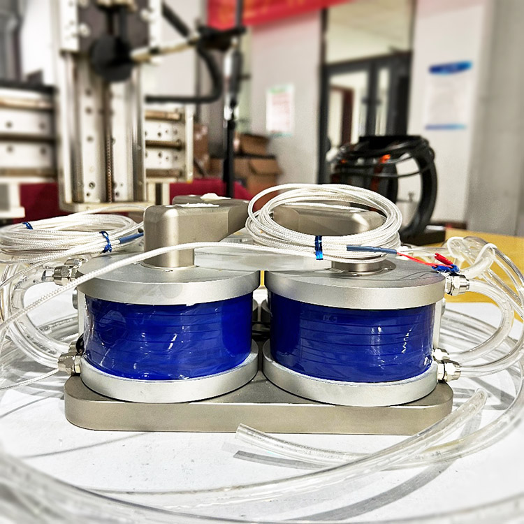
Overall Dimensions: 240mm(L) x 226mm(W) x 125mm(H)
Coil spacing
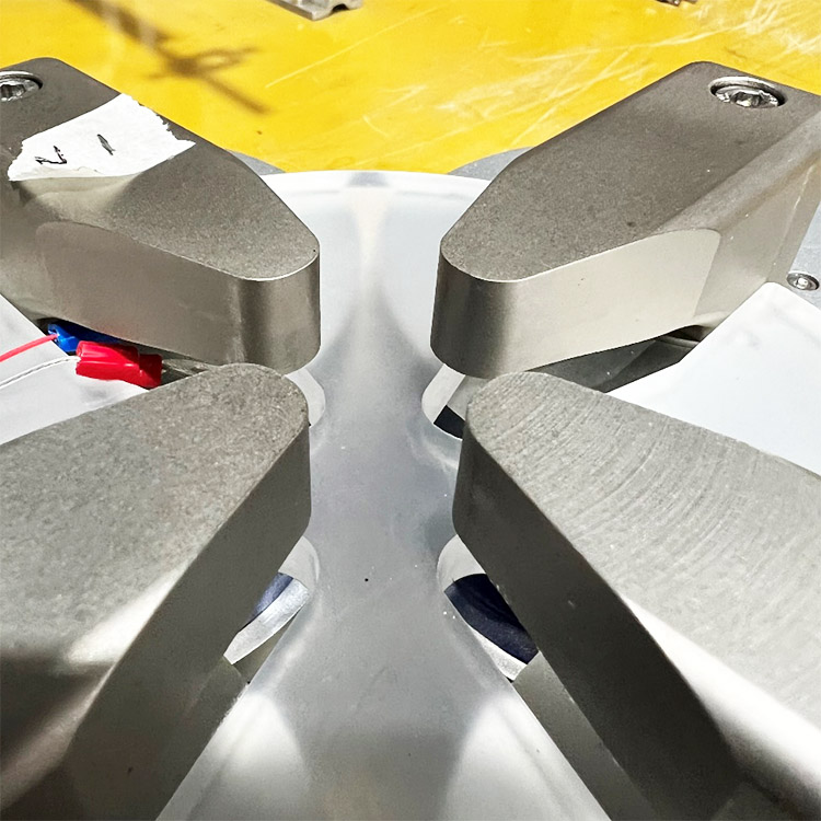
Pole face diameter: 15 x 9.6mm
Air gap range: 26mm
Weight: 23.6kg
| Performance test report | |||||||
| Introduction | |||||||
| 1. Test purpose | |||||||
| Through the analysis of the test results, the evaluation of the product performance is obtained; Evaluate whether the test product meets the technical requirements; Provide reference data for product design and after-sales service, and provide a strong basis for leaving the factory. |
|||||||
| 2. Basic information | |||||||
| Product Name: Quadrupole clamp electromagnet |
Product model: | DXFP-4015 | |||||
| Test time: | Nov. 27, 2023 | ||||||
| 3. Testing environment | |||||||
| The detection environment is closer to the actual environmental conditions used by the user, including factors such as lead wire length and ambient temperature. The time is selected in the time interval where the fluctuation of the geomagnetic field is small. Before the test, the instruments required for the test were turned on and warmed up in advance and the measurement environment was recorded, as shown in Table 1. | |||||||
| Measurement environment | |||||||
| Environment temperature |
Product initial temperature |
Lead length | Environmental magnetic field |
||||
| 7.0℃ | 7.0℃ | 0.5m | 0~30000nT | ||||
| Table 1 Measurement environment data | |||||||
| Magnetic field parameter test | |||||||
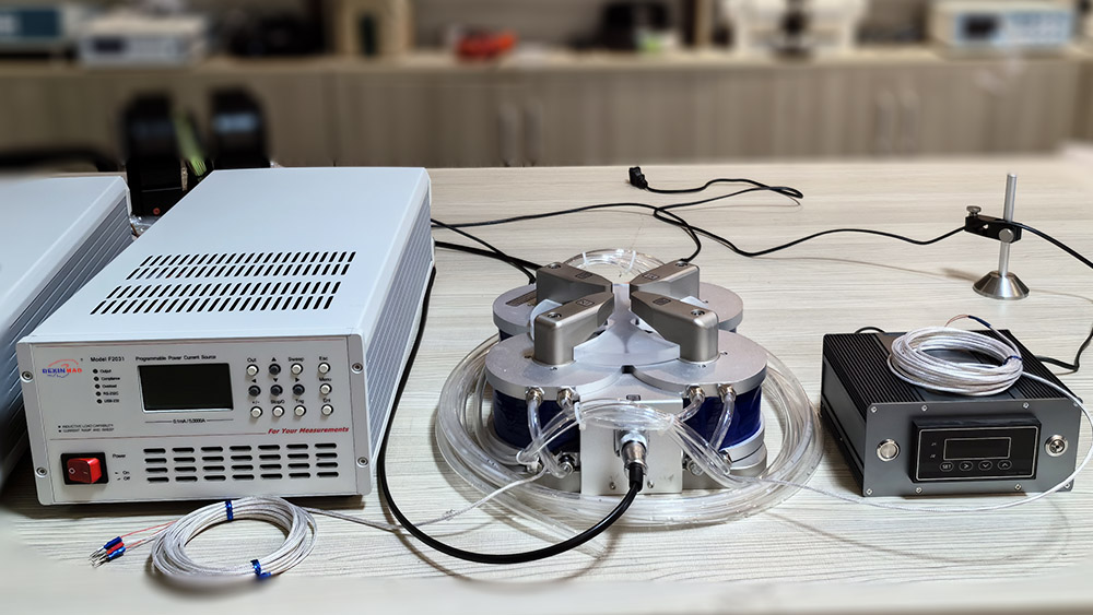
| 1. Using the device | |||||||
| DX-F2031 power supply DX-180 Gauss Meter |
|||||||
| 2. Magnetic field measurement | |||||||
| This product uses the following measurement methods: Fixed-point measurement: measure the magnetic field at the target point |
|||||||
| Magnetic field strength | |||||||
| No. | Display current (A) | Display voltage Voltage (V) | Magnetic field strength(Gs) |
||||
| Antipole No. 1 | 1 | - | 420.21 | ||||
| Antipole No. 1 | 2 | - | 840.81 | ||||
| Antipole No. 1 | 3 | - | 1258.54 | ||||
| Antipole No. 1 | 3.6 | - | 1520.80 | ||||
| Antipole No. 2 | 1 | - | 431.73 | ||||
| Antipole No. 2 | 2 | - | 849.81 | ||||
| Antipole No. 2 | 3 | - | 1268.29 | ||||
| Antipole No. 2 | 3.6 | - | 1519.13 | ||||
| Extra antipolar | 1 | - | 511.39 | ||||
| Extra antipolar | 2 | - | 1012.37 | ||||
| Extra antipolar | 3 | - | 1506.15 | ||||
| Four poles | 1 | - | 606.11 | ||||
| Four poles | 2 | - | 1212.38 | ||||
| Four poles | 3 | - | 1807.58 | ||||
| Four poles | 3.6 | - | 2156.49 | ||||
| Table 2 Magnetic field strength data | |||||||
| Magnetic field uniformity | |||||||
| No. | Area | Current | Max | Min | Uniformity | Note | |
| Antipole No. 1 | 6*6*1mm | 3.6A | 1607.66Gs | 1455.13Gs | 5.71% | ||
| Antipole No. 2 | 6*6*1mm | 3.6A | 1607.41Gs | 1458.70Gs | 5.71% | ||
| Extra antipolar | 6*6*1mm | 3A | 1574.68Gs | 1460.35Gs | 4.55% | ||
| Four poles | 6*6*1mm | 3.5A | 2257.75Gs | 2083.89Gs | 4.70% | ||
| Table 3 Uniformity data | |||||||
| Electrical parameter test | |||||||
| 1. Using equipment | |||||||
| Digital multimeter Impedance analyzer |
|||||||
| 2. Test method | |||||||
| The digital instrument with bridge circuit and voltammetry is used for measurement. The measurement results are shown in the table below. | |||||||
| Resistance R measurement | |||||||
| No. | Product temperature | Measuring resistance | ResistanceR@20℃ | ResistanceR@85℃ | |||
| 1 | 7.0℃ | 4.960Ω | 5.275Ω | 6.853Ω | |||
| 2 | 7.0℃ | 4.930Ω | 5.244Ω | 6.811Ω | |||
| Table 4 Resistance R data | |||||||
| 3. Test method | |||||||
| This product uses the following measurement methods: Using magnetic field temperature rise measurement: given the limit working time and maximum temperature under the target magnetic field current required by the user. Maximum current temperature rise measurement: Measure the ultimate working time and maximum temperature under the maximum safe current that the product can withstand Measure the data on temperature, time and current of the entire coil. The measurement results are shown in the table below. |
|||||||
| Temperature rise test | |||||||
| Current[A] | Working time[min] | Initial temperature[℃] | End temperature[℃] | ||||
| 3.6 | 120 | 16.1 | 31.8 | ||||
| Current[A] | Working time[min] | Initial temperature[℃] | End temperature[℃] | ||||
| 2.4 | 60 | 21.7 | 26.2 | ||||
| Note | 2.4A@1T running for one hour: uniformity 0.12% | ||||||
| Table 5: Relationship data between temperature, working time and current | |||||||
| Conclusion | |||||||
| The magnetic field and electrical performance of the product meet the requirements of the corresponding technical parameters. The final performance of the product is subject to this document. | |||||||
