Multi-dimensional Magnetic Field Testing System
The DX-2012F multi-dimensional high-precision fully automatic digital magnetic measurement system is an automatic digital high-precision magnetic measurement platform with the highest international level developed by Dexinmag company.
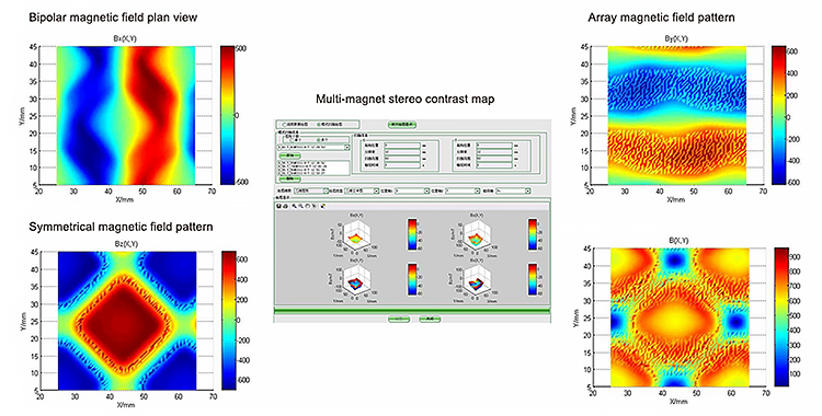
It can test the three-dimensional magnetic field distribution of AC and DC magnetic fields in any shape space with high precision, the three-dimensional distribution of magnetic structures on the surface of various shapes, uniform distribution, multi-pole magnetic ring, N/S magnetic pole distribution, motor magnetic field, superconducting magnetic field, magnetic resonance imaging magnetic field and many other magnetic field characteristics tests; It is then drawn into various graphics, stored data and saved for printing.
It is suitable for all kinds of AC and DC magnetic field magnetic research and has been widely used by many domestic and foreign aerospace military and scientific research units.

Characteristic of DX-2012F Multi-dimensional Magnetic Field Testing System
1. Wide range of measurement: Space measurement range is 200mm x 200mm x 200mm (X, Y, Z)(it can be customized, please advise if there's a special requirement), free tour optional three directions, and will reach 5Axis platform when rational platform attached to it. The translation is meticulous(Resolution ratio: 0.00039mm), Positional accuracy 0.01mm, Repeat positional accuracy<0.005mm, Rotation travel angle resolution ratio <0.0002°, positional accuracy 0.01, Repeat positional accuracy <0.005°, Velocity of movement can be divided into 2-64 classes. Fine distribution of measure space on the physical space.
2. High accuracy of system measurement: Using high-precision digital Gauss meter (one-dimensional or multi-dimensional) equipped with micro Hall probes (one dimensional ɸ0.5mm, two-dimensional ɸ1.2mm, three-dimensional ɸ1.2mm)make space and surface magnetic measurement up to higher accuracy. (One-dimensional precision can be up to ± 0.05% of the reading, range±0.005. Three-dimensional precision can be up to ± 0.10% of reading, range ± 0.005 )
3. Automation and Digitization: The real-time control and data acquisition controlled by computer, system software design measure processes that can be divided into many forms, user can directly enter data parameters of the measured object for fully automated measurement, and data is automatically recorded and saved, based on test data system can generate one dimensional, two-dimensional, three-dimensional graphics and measurement data logging, database format is Access and print the chart.
4. Flexible combinations: Three-dimensional translation platform and rotation platform can be assembled in many suitable situations for various measurement methods to meet the needs of the different measurements, system software covers control and data acquisition, and software function can also be extended as required, realizing full automation of unmanned monitoring measurement.
5. Gauss meter tested by National Institute of Metrology China; System software registered and approved by CPCC(Copyright Protection Center of China)

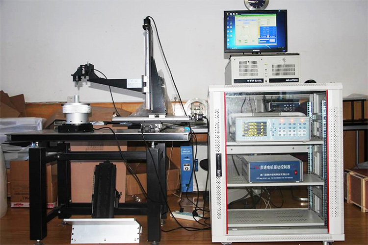
System configuration
The system consists of a PC (equipped with control software), a high-precision Gauss meter (one-dimensional or three-dimensional), the probe that agrees with the Gauss meter, displacement multidimensional electronic control units as well as the displacement station controller. As shown in the schematic picture above, the system can be simply divided into two parts, one is used to collect the data, and the other part is only displacement, the two parts make up the acquisition system.
The displacement part consists of an electronic control displacement module and displacement station controller, by operating the PC software to send a command to the controller, the controller will drive the electric displacement units to control each axis motion according to the command, the parameters of this electronically controlled displacement table can be customized by users (table size, the length axis of motion, movement, the number of dimensions), realizing scan of various angles and various shapes within the allowable range.
CNC Multi Axis Platform
Axis can be selected, panning trips and rotating table diameter can be selected
|
Direction |
Panning trips |
Resolution |
|---|---|---|
|
X |
50mm-4000mm |
0.00039mm |
|
Y |
50mm-2000mm |
0.00039mm |
|
Z |
50mm-2000mm |
0.00039mm |
|
T(Rotary table) |
360° |
0.0002º |
|
θz(Rotary table) |
360° |
0.0002º |
High-precision full digital Gauss meter
|
Model |
Resolution and range |
Resolution |
|---|---|---|
|
DX-360 |
10nT-30T |
±0.15%±0.005 range of the reading |
|
DX-210 |
10nT-30T |
±0.10%±0.005 range of the reading |
|
DX-180 |
10nT-30T |
±0.05%±0.005 range of the reading |
|
DX-160 |
100nT-3T |
±0.20%±0.005 range of reading |
Sample Test
Plane magnetic field
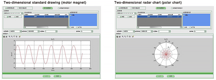
Manual control-When using manual control, the motion table will move the probe according to the coordinate points and positions entered manually. After the movement is finished, the reading is made on the software interface when the reading is stable. It is used to measure the magnitude of the magnetic field at the specified position and is suitable for single-point measurement. Pay attention to the position of the probe when using it. When used in high-precision motion tables, the resolution of motion control can reach micrometers. Flow control-When using flow control, you need to measure the motion path of the stage first. After selecting the path, enter the moving step and the number of steps for each axis in sequence. When the motion table moves, the probe will be moved according to the set path to measure the magnetic field of each point on the path. Flow control is also used to measure the magnitude of the magnetic field on a line in a plane and can be plotted.
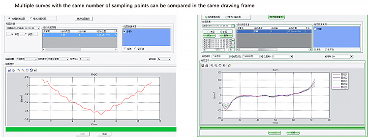
Flow control drawing interface
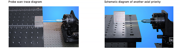
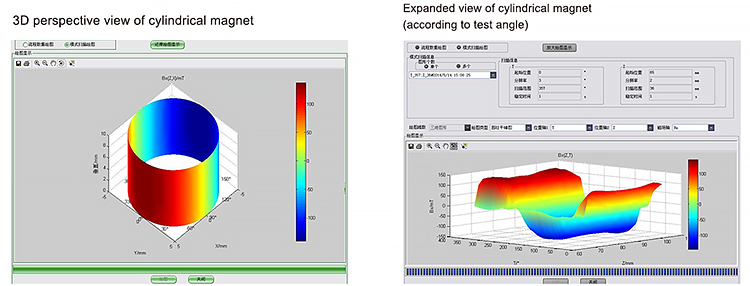
Scan mode - Set the scan area size and the interval length of each scan point as required when using the mode scan. After setting, move the probe to the beginning of the test for manual testing. The scanning process is S-shaped, the scanning path is shown in the figure below, and one axis is performed first.l In addition to horizontal plane scanning, vertical plane scanning can also be achieved by changing the axis of motion. In vertical plane scanning, the scanning trajectory is still S-shaped, and the axial sequence can also be set by changing the axial sequence.
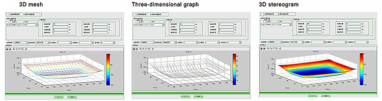
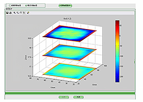
Three-dimensional drawing of space magnetic field(Drawing according to displacement amount, displacement 1mm)
Adding the third axis under the premise of plane scanning can scan different planes to form a set of three-dimensional drawings.
Cylindrical surface magnetic field, motor
Process control-When using process control, you need to adjust the probe to a suitable height and ensure that the probe will not be impacted when the motor is rotating. After selecting the height, enter the moving step and the number of steps in each axis in order. When the motion table moves, the probe will be moved according to the set path to measure the magnetic field of each point on the path. Flow control is also used to measure the magnetic field strength on a perimeter surface around a cylinder.
Mode scan drawing interface
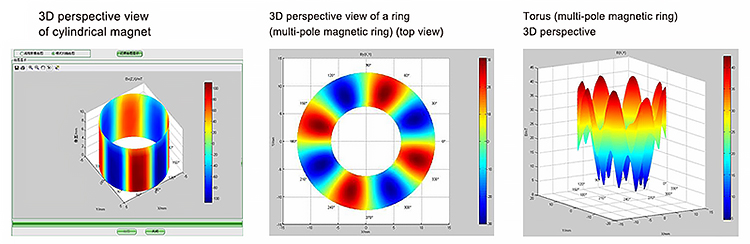
Other special magnets and drawings

Schematic diagram of the whole cylindrical magnet and motor overall measurement feature

Schematic diagram of bipolar motor test probe
Home > Measuring Equipment > Magnetic Field Mapping > Product Introduction
Customization is available, please let us know your requirements, and we will design a professional plan for you. Thank you!
Dexinmag® • 2025